An MPPT (Maximum Power Point Tracker) is an electronic high-frequency DC to DC converter. They take the DC input from the solar panels, change it to high-frequency AC, and convert it back down to a different DC voltage and current to exactly match the panels to the Required Output Load (E.G. Battery, Load Center, & Motor Pump).
- MPPT Technology nowadays available at almost all solar application (Due to their High efficiency):
- Off-Grid systems: MPPT Charge Controller.
MPPT technology at Charge controller allows a PV (Photo-Voltaic) array to deliver the maximum amount of energy to a battery bank.
MPPT charge controllers gained popularity in the early 2000s when manufacturers released highly reliable and accurate versions that allowed users to maximize the charging ability of their PV array and, in some cases, reduce the required PV array size for battery charging compared to some of the older technology.
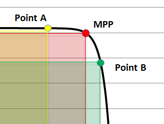
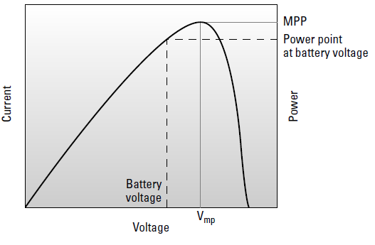
MPPT controllers take the power from a PV array at the MPP, regardless of the required battery voltage, and deliver that same amount of power (minus efficiency losses, of course) to the battery bank because they’re able to reduce the voltage from the array to the battery’s required level. And because power is the product of voltage and current, if the voltage is decreased, the current is increased in order to keep the same power level. MPPT controllers boost current into the battery bank in relation to the current received from the array.
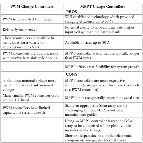
The pros and cons of MPPT controllers
- On-Grid systems: On-Grid (Grid-Tied) Inverter.
All grid-direct inverters employ MPPT to produce as much power as possible from the PV array. MPPT allows the inverter to harvest the maximum amount of power and deliver it to the load center, just like some charge controllers (as seen above) use it to deliver the maximum amount of power to a battery bank.
Working Principle
After evaluating energy production and consumption of the client, you need to size the Array to Meet Your Client’s Energy Consumption; you need to calculate power values and temperature-adjusted voltages & to check the maximum current input of PV on-grid systems.
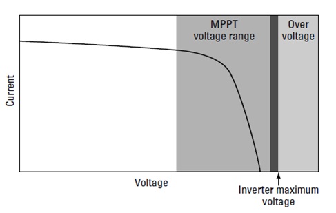
On the inverter’s DC side (which is connected to the array), there’s a minimum voltage required to allow the inverter to produce the maximum amount of power from the array -as the client expect their arrays to produce the maximum amount of energy possible- and a maximum voltage that can be applied without damaging the inverter.
Matching Power Values for an Array and an Inverter
All inverters are rated by their maximum continuous power output, which is measured in watts or kilowatts. This value is the AC power output.
Inverters actually limit their power output, so you can use this value to figure out the maximum power input coming into the inverter from the PV array.
When you look at PV module ratings, you find that the power output ratings are based on standard test conditions (STC) where the cell temperature is 25degrees Celsius and the intensity of the sun is equal to 1,000 W/m2.
PV modules rarely operate in these conditions due to the motion of the sun across the sky and increased PV operating temperatures.
- The power input coming into the inverter is typically considerably less than the rated values.
- Both the inverter and the array (along with all the other equipment in a grid-direct system) have efficiency losses that must be taken into account.
You can quickly estimate all of these system inefficiencies by adopting the industry standard that any PV system will operate at approximately 80 percent of overall system efficiency.
VIP: It's recommended to oversize modules power by (10~20%) more than Inverter Rated Power.
The inverter’s DC voltage window
Inverter’s voltage window consists of a maximum input voltage that you must stay under if you want to avoid damaging the inverter and a minimum voltage you must stay above to keep the inverter operating at the array’s maximum Power Point. As a PV system designer, you need to identify these values from a spec sheet and make sure the array can operate within this window throughout the year. If you allow the array to move outside this window, you risk damaging the inverter or shutting down the system for the day.

The minimum and maximum DC voltage values dictate the number of modules that can be placed in any string that’s connected to an inverter.
Calculating the modules’ maximum DC voltage contribution
As the temperature decreases, a PV module’s voltage actually increase (voltage and temperature therefore have an inverse relationship).
To make sure an array’s voltage never exceeds the inverter’s input value, you need to adjust the modules’ STC open circuit voltage value (Voc) for cold temperatures; this value is reported on spec sheets.
Applying the adjusted open circuit voltage to come up with the right number of modules in a string
Figuring out the modules’ minimum DC voltage contribution
On the other end of the voltage window is the minimum power point tracking voltage. If the voltage from the array ever drops below this value — usually due to high heat conditions that occur on the sunniest days (as in the days system owners expect their arrays to produce the maximum amount of energy possible) — the inverter won’t be able to continue operating and will shut down. Although this scenario won’t damage the inverter, it may damage your reputation. If your client sees his inverter shut down on a bright, sunny day because the voltage isn’t high enough.
But increasing Number of Modules per string- by 1~2 Modules- than minimum number of modules calculated, is the best choice due to degradation in Module`s Power(voltage) over its long life. So that to assure you always fit inside the voltage window.
- Pumping systems: Pumping Inverter.
Almost all Solar Pumping inverters employ MPPT to produce as much power as possible from the PV array. MPPT allows the inverter to harvest the maximum amount of power and deliver it to the Motor pump, just like some charge controllers & Grid Tied Inverters (as seen above) use it to deliver the maximum amount of power to a battery bank & Load center.
Advanced solar pumping inverters convert DC voltage from the solar array into AC voltage to drive pumps directly without the need for batteries or other energy storage devices. By utilizing MPPT (maximum power point tracking), solar pumping inverters regulate output frequency to control the speed of the pumps in order to save the pump motor from damage.
- Picking the temperature to use in MPPT calculation:
The high temperature Record: By designing with the record high temperature in mind, you ensure that the PV array will operate in all conditions.
Accounting for mounting in your calculation
To estimate a PV module’s temperature at the hottest time of the year, you should add one of the following temperatures to the ambient temperature:
- 35 degrees Celsius for arrays with fewer than 15 cm between the backs of the modules and the mounting surface
- 30 degrees Celsius for arrays with more than 15 cm between the back of the array and the mounting surface
- 25 degrees Celsius for arrays that are mounted on top of a pole
By adding these values to the ambient temperature, you can arrive at a best estimate for your array’s operating temperature — the temperature you expect to see at the module level if you were to measure the temperature in the middle of the summer.
Believing in Solar Market Egypt`s role in facilitating Solar companies and those interested in solar energy, in the calculation for each of the MPPT Design in:
- On-Grid Inverter: SM On-Grid designer tool.
- Pumping Inverter: SM Pumping designer tool.
- Charge Controller: SM MPPT Charge Controller designer tool
Solar Market Egypt developed a group of software tools to help you as A PV system designer and installer, to size the optimal number of solar modules & strings to be matched with different MPPT Solar systems in a quick & efficient way:


